First step is to check the physical size of each gate through a dimensional report.
Gates should always be made by using multiple rough and fine electrodes to ensure that the electrode wear will not cause any imbalance.
We suggest never to spark more than 4 cavities with the same rough electrode, and to then follow up with a fine electrode.
EDM steps:
- Rough spark all gates with minimum 1 electrode per 4 gates.
- Check electrodes for wear.
- Fine spark all gates with 1 fine electrode and check for electrode wear.
- If wear is within acceptable limit the gates are done.
- If the wear is outside of the acceptable limit go over all gates again in the opposite direction with a new fine electrode.
- Repeat the process until wear is acceptable.
Verification steps:
- Set the holding pressure to zero.
- Set the holding time to zero.
- Set the screw recovery delay time to about a value close to an estimated holding time.
- Set the cooling time to a value such that you know that the part will be cool enough to eject.
- Set your injection speed to the value obtained from the Viscosity Curve study.
- (Viscosity = Peak Injection Pressure x Fill Time x Screw Intensification Ratio)
- With the rest of the settings the same as you had in the viscosity study, start molding.
- Only by adjusting the transfer position, mold parts that are just short. If there is a visible cavity imbalance, then the ‘biggest’ part should be just short.
- Make three such shots and take the average weight of each cavity and plot a graph
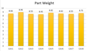
Check the %variation between the maximum and the minimum fill cavities. In most cases, the % variation should not be greater than 5%. For tight tolerance parts, the variation should not be more than about 3%. If the tolerances are large, variation more than 5% is acceptable. More importantly, it is the final quality of the part that should be checked to see it there is need to tighten up the cavity balance. For example, the Cpk values of all the parts from all the cavities is a good measure. The following should be considered:
- Amorphous materials can tolerate more imbalance than crystalline materials.
- Tighter the tolerances, lesser should be the variation.
Venting is a very big contributor to plastic fill and can have a big impact on the cavity balance although the gate and runner sizes are the same. Make sure that the venting is the same for all cavities.
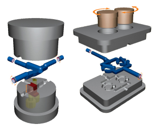
In tools where the balance is of extra importance we recommend the use of dynamic rheological control inserts.
They add a great way to control the fill balance between cavities without even taking the tool down from the press.
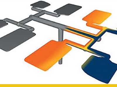
[ut_two_thirds]The cause is the natural stratification of melt within a flow channel into zones, or “laminates,” of different temperature and viscosity. This results from the greater shear heating of melt close to the channel wall. When the melt channel divides in a runner system, the melt heading toward one cavity or set of cavities may be more fluid than the melt split off in the opposite direction. Thus, despite exact cavity replication and balance in the mold steel, parts are formed under different conditions, just as if they were molded at different melt temperatures, fill rates, and packing times and pressures. [/ut_two_thirds]
[ut_one_third_last]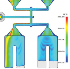 [/ut_one_third_last]
| Runner with central flow The fast moving high shear material flows symmetrical along the edges of the runner |
Runner with modified flow The fast moving high shear material is set to one side of the runner steering the flow pattern in to the cavity |
 |
 |
Result before and after flow modification (no gate geometry was changed between the trials):
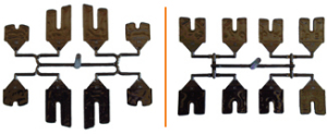
iMarc single axis for balance between cavities
iMarc multi Axis for fill pattern within a single cavity

For any help with gate balance please feel free to contact us at The Tool Hub.


