


[ut_two_thirds]
There are many factors that play a role in the shrinkage that you will experience in your finished molding.
Resin nature:
Semi-Crystalline (High shrink rate)
Amorphous (Low shrink rate)
Below you can see more information on Semi-Crystalline Vs Amorphous resin types, and how they group on the shrink rate scale.
[ut_one_half] 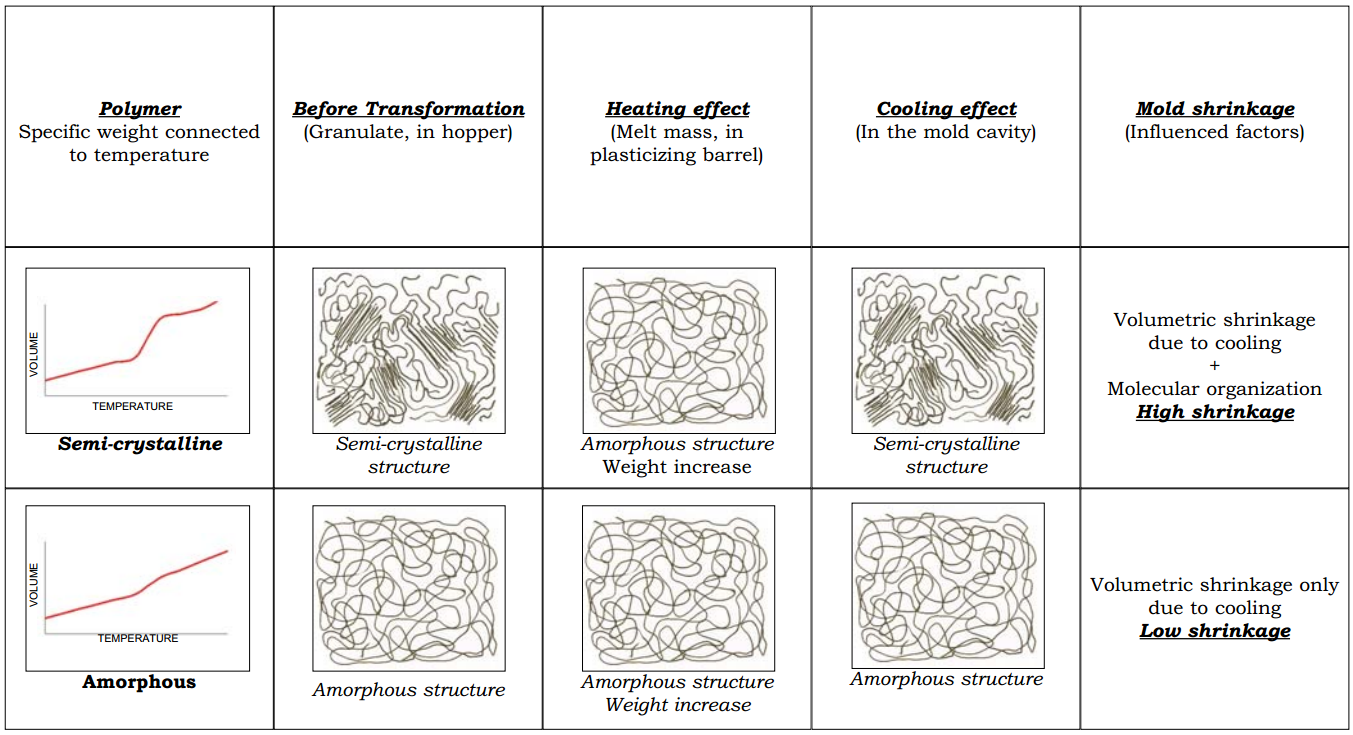 [/ut_one_half]
[ut_one_half_last]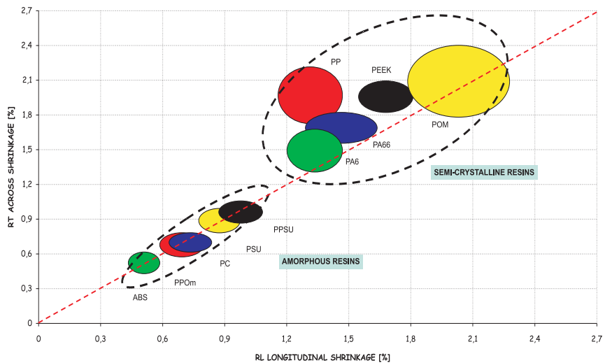 [/ut_one_half_last]
Rein fillers:
Glass fibre
Glass beads
Minerals
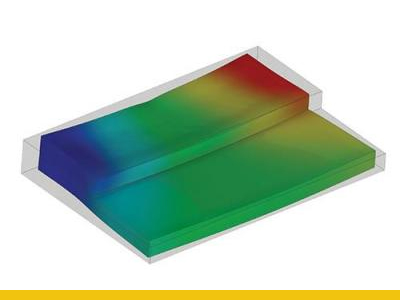
Fibrous fillers tend to align their strands with the flow of the material.
This can give big differential shrinkage across your part and therefore increase warpage and uneven dimensions.
Minerals and beads are isotropic in their shape and are distributed evenly in the melt mass.
This gives much less differential shrinkage and improved planarity plus dimension stability (in semi-crystalline resins)
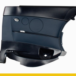
Dimensional stability comparison for a plate 120x80x3.5 mm with different resins and fillers.

Part geometry
| Thicker wall sections will increase the shrink rate | [ut_icon icon=”fa-arrow-up” size=”fa-lg” align=”alignnone”] |
| Longer flow lengths will increase the shrink rate | [ut_icon icon=”fa-arrow-up” size=”fa-lg” align=”alignnone”] |
Processing parameters
| Increased cavity pressure will decrease the shrink rate | [ut_icon icon=”fa-arrow-down” size=”fa-lg” align=”alignnone”] |
| Increased holding pressure time will decrease the shrink rate | [ut_icon icon=”fa-arrow-down” size=”fa-lg” align=”alignnone”] |
| Longer cooling time will decrease the shrink rate | [ut_icon icon=”fa-arrow-down” size=”fa-lg” align=”alignnone”] |
| Higher mould temperature will increase the shrink rate | [ut_icon icon=”fa-arrow-up” size=”fa-lg” align=”alignnone”] |
| Higher melt temperature will increase the shrink rate | [ut_icon icon=”fa-arrow-up” size=”fa-lg” align=”alignnone”] |
[/ut_two_thirds]
[ut_one_third_last]
| Material Name | Shinkage % |
| ABS | 0.4 – 0.7 |
| CA | 0.3 – 0.7 |
| CAB | 0.2 – 0.5 |
| CP | 0.2 – 0.5 |
| EVA | 0.7 – 2.0 |
| FEP | 3.0 – 6.0 |
| GPPS | 0.2 – 0.8 |
| HDPE | 1.5 – 4.0 |
| HIPS | 0.2 – 0.8 |
| LDPE | 1.5 – 4.0 |
| PA6 | 1.0 – 1.5 |
| PA66 | 1.0 – 2.0 |
| PBT | 1.5- 2.0 |
| PC | 0.6 – 0.8 |
| PES | 0.6 – 0.8 |
| PET | 1.8 – 2.1 |
| PMMA | 0.2 – 1.0 |
| POM | 2.0 – 3.5 |
| PP | 1.0 – 3.0 |
| PPO | 0.5 – 0.7 |
| PSU | 0.6 – 0.8 |
| PTFE | 5.0 – 0.9 |
| PVDF | 2.0 – 3.0 |
| SAN | 0.2 – 0.6 |
| PP/EPDM | 1.0 – 2.0 |
| PUR/TRU | 0.5 – 2.0 |
| SBS | 0.4 – 1.0 |
| SEBS | 1.0 – 5.5 |
| DMC | 0.5 – 0.2 |
| MF | 0.6 – 1.0 |
| PF | 0.7 – 1.2 |
[/ut_one_third_last]
As toolmakers there are a few things we can do to help you control the shrink rates.
Good and uniform cooling are critical elements.
Tight shut off with the right amount of venting can help with the cavity pressure.
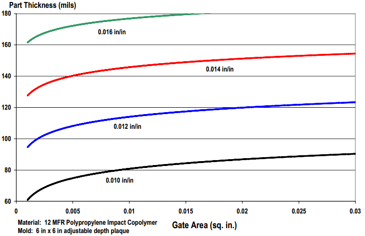
Gate size, placement and design will aid with increased holding pressure.
Below you can see a graph that shows how a bigger gate size can help decrease the shrink rate:
Good luck!
If you have any questions or just want some quick support, please feel free to drop us a line or give us a call. We are always here to help.Contact us