


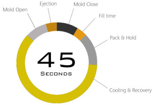
Injection moulding process is cyclic in characteristic. Cooling time is about 50 to 75% of the total cycle time. Therefore, optimising cooling time for best performance is very important from quality and productivity point of view.
The real objective here is to control the cooling rate and temperature of the parts so they can be ejected at the earliest possible time, while maintaining the desired properties and dimensions.
Cooling channel design – location and size and type – should ensure that melt freezes uniformly inside the mould. Cooling channel design must be analyzed with the help of a Mold flow report.
Understanding Heat Exchange in the mould
During every injection moulding cycle following heat transfers take place:
- from the hot melt to mould steel (heat input to the mould) and
- from mould steel to coolant flowing through cooling channel of the mould. (heat removal from the mould)
If heat input is more than heat removal, then the mould temperature would keep on increasing from cycle to cycle. Therefore moulding quality would not be constant from cycle to cycle. The moulding quality would be erratic- i.e. varying from cycle to cycle. Therefore, there is a need to balance between the heat input and heat removal in the mould after the desired mould surface temperature is reached. In other words, removal of heat by circulating coolant through the mould cooling channel would arrest the rise of mould temperature above the desired value. In practice, it may not be possible maintain constant mould temperature with respect to time. However, the mould temperature would fluctuate between two values around the desired value.
Quick design tips
Cooling channel diameter should be more for thicker wall thickness:
For wall thickness up to 2 mm, channel diameter should be 8 – 10 mm.,
For wall thickness up to 4 mm, channel diameter should be 10 – 12 mm.,
For wall thickness up to 6 mm, channel diameter should be 10 – 16 mm.
The difference between the inlet and outlet water temperature should be less than 2 to 5 degrees C. However, for precision moulding, it should be 1 degree C or even 0.5 degree C.
It is often difficult to accommodate cooling channels in the smaller cores or cores with difficult geometry. In such case the core should be made of Beryllium copper or Ampco which has high thermal conductivity. These core inserts should be connected to a cooling channel to best dissipate the heat.
It is often a good idea to add thermocouples at one or two places in core as well as cavity to monitor the temperature of mould.
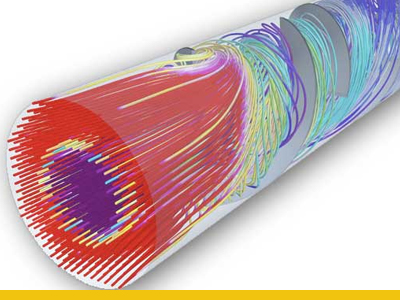
Turbulent Flow
Achieving a turbulent flow is a good way to increase the heat transfer without having to alter anything in an existing tool.
Studies have shown that for the same net flow through a cooling channel a turbulent flow can transfer as much as 150-500% more heat from the tool steel.
Turbulent flow begins when the velocity of fluid in a channel increases to a critical level. Above this critical velocity, vigorous internal mixing of the fluid occurs as it flows. This improves heat transfer by mixing warmer fluid near the wall of the cooling passage with the relatively cooler interior fluid. The precise velocity for turbulent flow depends on several variables, including the cooling passage geometry, fluid viscosity, and roughness of the pipe walls. The formula for a ratio known as Reynold’s number includes these variables. A Reynold’s number greater than 4000 denotes turbulent flow.
Boundary Layer
The boundary layer is defined as the area of the flow that has shear stress forces induced by the solid wall of the water block. What this basically means is that the boundary layer is the part of the moving water that is feeling the friction of the wall. The molecules of water that are closest to and touching the water block wall are not moving at all, but are stationary. As the distance from the wall increases, the molecules pick up speed until they are far enough away that the flow feels no effects from the wall.
The problem with having a boundary layer for heat transfer in a water block is that it is actually insulating the inner most layers of flow from being able to pick up the heat from the tool steel. This is especially true of laminar flow because the boundary layer is very thick. However, in turbulent flow the random action of the water molecules breaks up the boundary layer and disperses the majority of it, thus increasing the ability of all the water molecules to pick up heat from the water block wall.
Flow rate needed to achieve turbulent flow:
|
Pipe Size
|
ID of drilled passage (mm)
|
Min. flow rate for turbulent flow (L/min)
|
|
1/16 NPT
|
6.5
|
1.25
|
|
1/8 NPT
|
9
|
1.66
|
|
1/4 NPT
|
11
|
2.08
|
|
3/8 NPT
|
15
|
2.80
|
|
1/2 NPT
|
18
|
3.4
|
The best cooling system in the world won’t take away heat any faster than the molded part will give it up. Most unfilled resins transfer heat at a rate 1/10 to 1/25 that of steel. The outer walls of a thick part insulate the mold from the heat trapped in the center of the part. The message here is that for very thick part, the cooling system will have relatively little effect on cycle time.
Optimal flow economy
An increase high above the threshold for turbulent flow is not very beneficial. For optimal cooling economy we recommend to stay in the green zone.
